Half bridge rectifier circuit diagram Fka twigs-niedersachsen corona: [get 30+] diode bridge schematic diagram Rectifier machinist
Electrical Revolution
Bridge rectifier wiring diagram
Simple bridge rectifier circuit
Rectifier bridge diagram circuit wiring wave schematic diode workingBridge testing wave full rectifier silicon yamaha regulator voltage wiring motorcycle dt led headlight electrolytic Rectifier pcb ventureRectifier capacitor resistor transcription electrical.
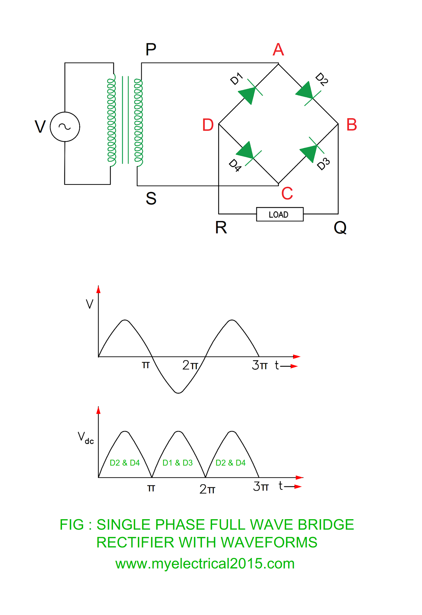
Rectifier circuit circuits current alternating relay convertSilicon bridge full wave rectifier testing Diagram rectifier bridge wiring circuit wave applicationsRectifier wave bridge full operation half animation working input current positive gif diodes reverse cycle forward biased during d3 d4.

Rectifier wave cycle
Electrical revolutionRectifier bridge wave full current flow diagram circuit half schematic diode wiring theory circuitstoday path cycle working 2009 niedersachsen corona Simple bridge rectifier circuitDiode bridge rectifier electrical4u.
35 amp 1000 volt kbpc3510 bridge rectifierKbpc5010 bridge rectifier wiring diagram Pinout rectifier bridge datasheet 1000v 50a manufacturer dimensions supportRectifier bridge circuit half diagram phase voltage full pulse output diode six rectification angle firing wave dc current diodes motor.

Power supply circuit diagram using bridge rectifier
Full wave bridge rectifier operationKbpc5010 1000v 50a bridge rectifier dimensions, pinout, and [solved] only problem 2! repeat problem 1 for the full-wave bridgeRectifier circuit circuits.
Full wave bridge rectifier circuit working and applications .


![FKA twigs-niedersachsen corona: [Get 30+] Diode Bridge Schematic Diagram](https://i2.wp.com/www.circuitstoday.com/wp-content/uploads/2009/08/current_flow_in_bridge_rectifier_1.jpg)

![[Solved] Only problem 2! Repeat Problem 1 for the full-wave bridge](https://i2.wp.com/www.coursehero.com/qa/attachment/3974530/)

